Project 3 and 4 for DIY Design was the development of a key chain which could be 3-d printed. This keychain was used to make a silicon mold which could be filled with plastic to create copies of the original 3-D printed piece.
Final Images


Process
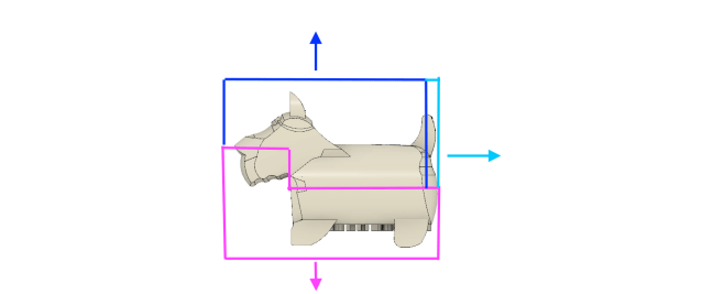
When deciding what to make as my keychain I decided to pick something I would find useful to have in multiple. Since I am the officer of a club sports team I figured I would use this opportunity to make a key chain for the officers. The design is the school mascot with goggles added to it.


Build Up In CAD
The stl for my file can be found here.

Rendering


Draft Analysis
Draft Analysis allowed me to see the draft angles on a part of the design. A green side is a draft angle higher than the maximum of the draft angle range (-.5°-+5°) . A red side indicates a side with a draft angle between the range. A blue side is a draft angle below the minimum of the draft range. I completed draft angle analysis for the x, y and z direction in order to determine the best parting lines for my mold. In an ideal design the color will be red along the parting line and green on one side of the parting line and blue on the other side of the parting line.
Y Direction
If my parting lines were in the x, z plane the molds would be removed in the y direction. The images below represent this possibility. While this mold would work for a large part of the design the feet and the ears present significant problems because blue sections are directly in front of and behind blue sections.


Z Direction
If my parting lines were in the x, y plane the molds would be removed in the z direction. The images below represent this possibility. This mold design would have a similar issue in the feet. In addition, the tail and/or the face would present a problem in the removal of the mold making this idea in ideal.


X Direction
If my parting lines were in the x, y plane the molds would be removed in the z direction. The images below represent this possibility. The lines on this design are much more ideal than the other design but there are still problems. These problems exist in the tail. In addition the blue line is not a strait line.


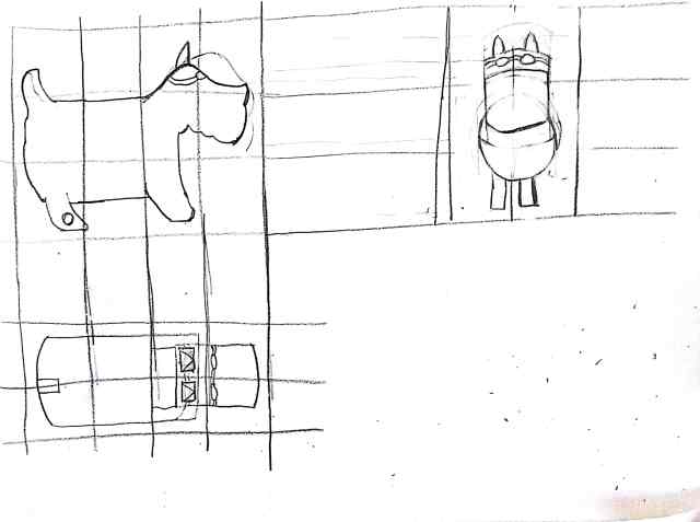
Mold Plan

Drawing of the plan to create the mold. Three straws are glued to the master to create weep holes at the ears and tails. The pour hole will be in the center of the back.
Fabrication Process: Making the Master
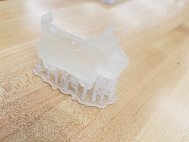


Fabrication Process: Making the Mold
The mold making process I used is based off of the instructional video found here.


Fabrication Process: Using the Mold


Final Keychains:


